Tone Matrix Part 2: Oscillators
Let's start with the core of the tone matrix: the oscillator. Unlike most synthesizers, which have lots of note adjustment, I'm fine with mine being fixed pitches. I do want more control over the wave-shaping, which comes standard with most synthesizers. The ADSR shaping will come later with the sound effects block, here I just want to focus on three output options:
- Square Wave
- Triangle Wave
- Sine Wave
Square Wave
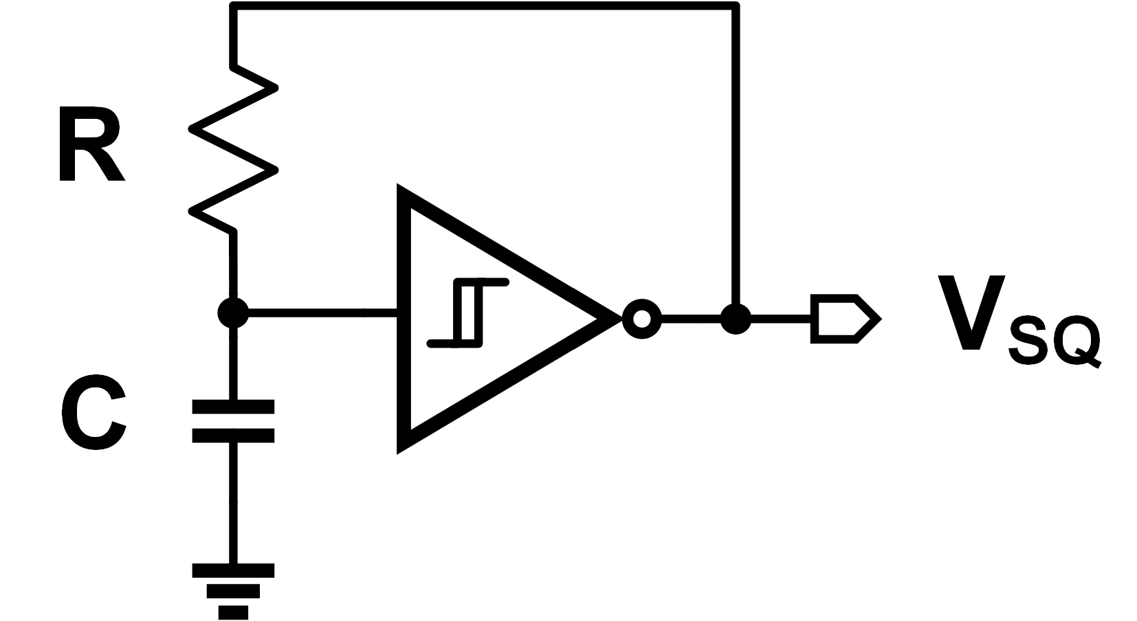
Starting with the square wave, I want to use a simple Schmitt trigger circuit, shown below. But how does it work?
A Schmitt trigger is a lot like an inverter, but with a wide hysteresis window. We can mathematically define an ideal inverter as:
$$V_{OUT} = \begin{cases} V_{DD} & \text{if $V_{IN} < V_{T}$} \ 0 & \text{if $V_{IN} > V_{T}$} \end{cases} $$
where $V_T$ is our “trip voltage” to change the outputs. Adding hysteresis to this means our transition window changes - it's not a constant trip point anymore. We get a bit of “memory” effect this way, as the next state depends on the last state. Mathematically, it looks like this:
$$ V_{OUT} = \begin{cases} V_{DD} & \text{if $V_{IN} < V_{T} - V_H$} \ 0 & \text{if $V_{IN} > V_{T} + V_H$} \ V_{OUT} & \text{if $|V_{IN} - V_H| < V_T$} \end{cases} $$
If we just connect it in feedback, it probably won't oscillate. It'll instead just lockup at a constant output voltage. Adding an RC network will cause oscillation - while the math might be awkward to prove, the intuition is simple. Assume the input node begins low, and the output starts high. This will charge up the capacitor slowly (at the $RC$ time constant rate). Once the cap gets to a sufficiently high voltage, the output switches and the capacitor discharges again. This is shown below visually:
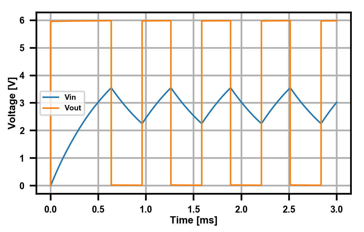
A “normal” $RC$ filter would has a time constant $\tau=1/RC$, so we would assume that's the frequency we get at the output. In reality, the hysteresis effect has a constant factor $\alpha$: $$f = \frac{1}{\alpha RC}$$ which is dependent on the height of the hysteresis window. In my simulations (above), with $R=150\Omega, C=4.7\mu\text{F}$, we get an output frequency of 1.59 kHz. This gives us $\alpha=0.88$, and we can say our square wave is done.
Triangle Wave
Alright, onto step two. Again, it's probably easiest to start from the mathematical perspective. Going from a square wave to a triangle wave is just an integration.
$$V_{TRI} = \int V_{SQ} dt$$
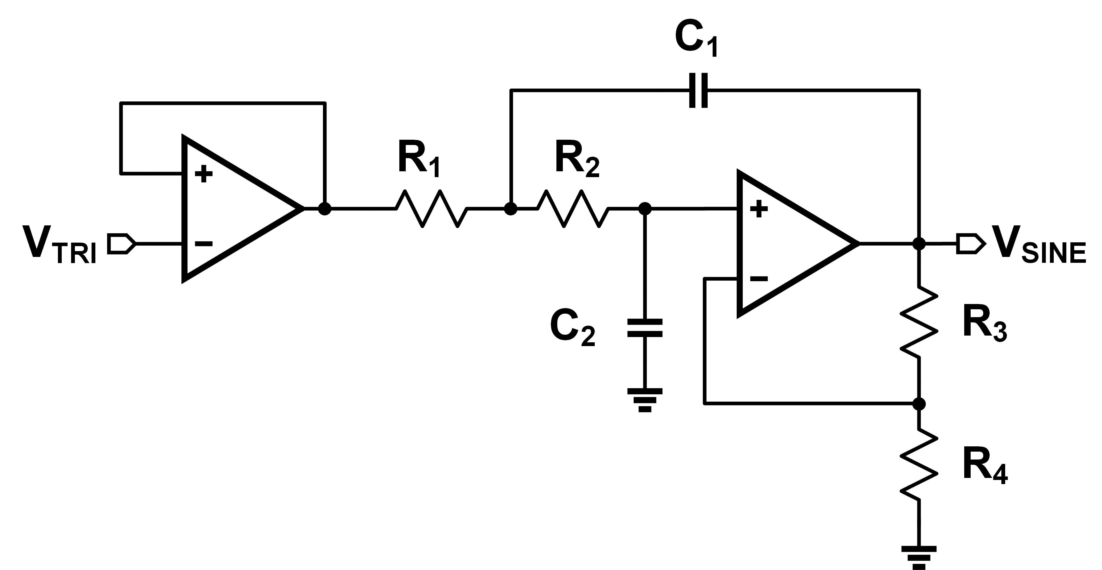
But how do we do that with circuits? With an integrator circuit (duh). The schematic is shown below:
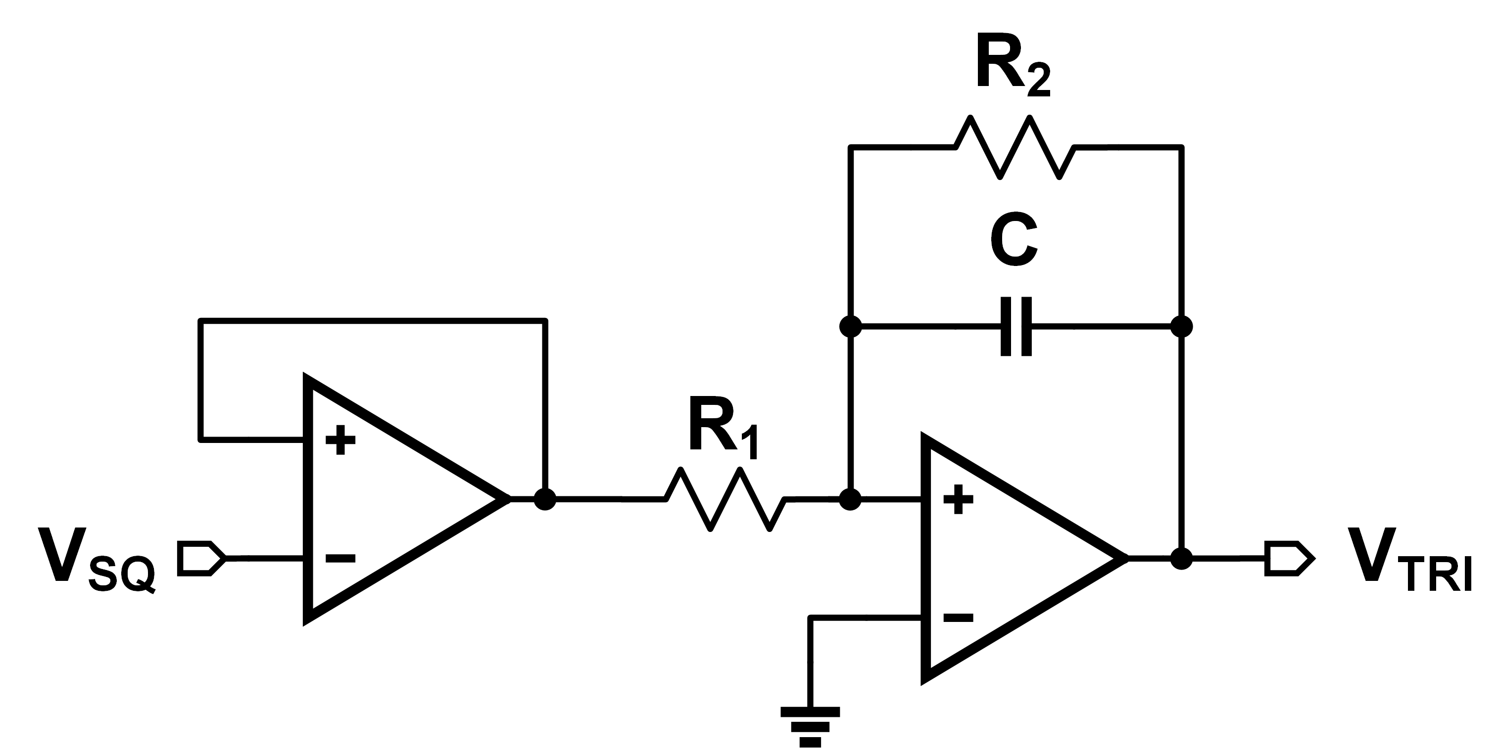 To prove this, we'll solve for $V_{TRI}$. Any op-amp circuit is solved the same way, doing KCL around the input nodes. The first op-amp is just a simple buffer, so we'll assume its output is also $V_{SQ}$. Looking at the second op-amp, we have:
$$\frac{V_{SQ}-0}{R_1} = \frac{0 - V_{TRI}}{\frac{1}{sC}||R_2}$$
You can do the math yourself, but the result you get is:
$$\frac{V_{TRI}}{V_{SQ}} = - \frac{R_2}{R_1} \frac{1}{1+sCR_2}$$
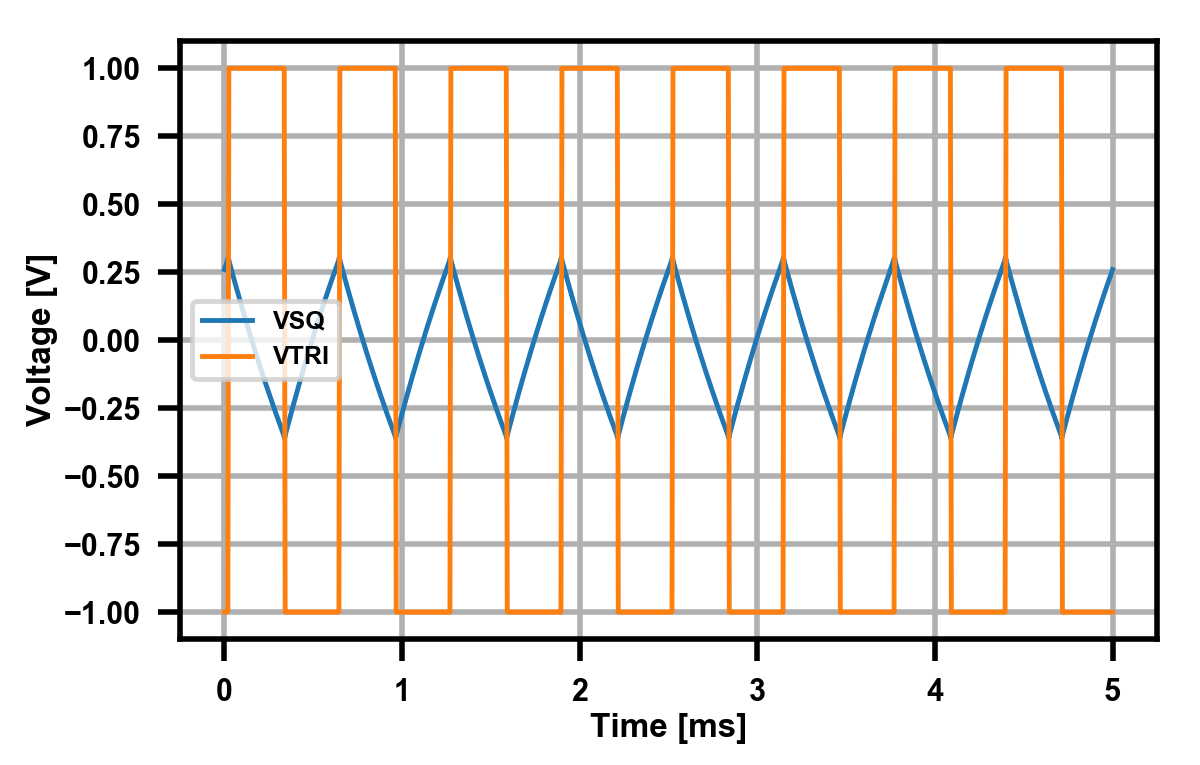
Up until the pole caused by \(CR_2\), we have constant gain \(R_2/R_1\). After that, we roll-off at 20 dB/decade. For frequency inputs after $CR_2$, the output is integrated. I tested it using \(R_1=100\Omega\), \(R_2=200\Omega\), and \(C=4.7\mu\text{F}\). My input was an square wave voltage source, with \(f=1.6\text{kHz}\).
One might ask, why do we need the feedback resistor $R_2$? We could get rid of it, then our transfer function would be the much simpler: $$\frac{V_{TRI}}{V_{SQ}} = - \frac{1}{sCR_1}$$ The problem lies with the op-amp offset voltage. In an ideal op-amp, the input terminals are at the same voltage (in feedback), so there is zero DC error. However, in a real op-amp, there will some small yet non-negligible DC voltage between the two (generally in \(\mu\(V range). Unfortunately for us:
$$\int^\infty \delta dx \to \infty$$
In other words, even a infinitesimally small error will eventually saturate and break our integrator. By limiting our DC gain to some finite amount, we can safely account for it. To prove this, I disconnect $R_2$ in the above schematic, and re-simulate with the following results.
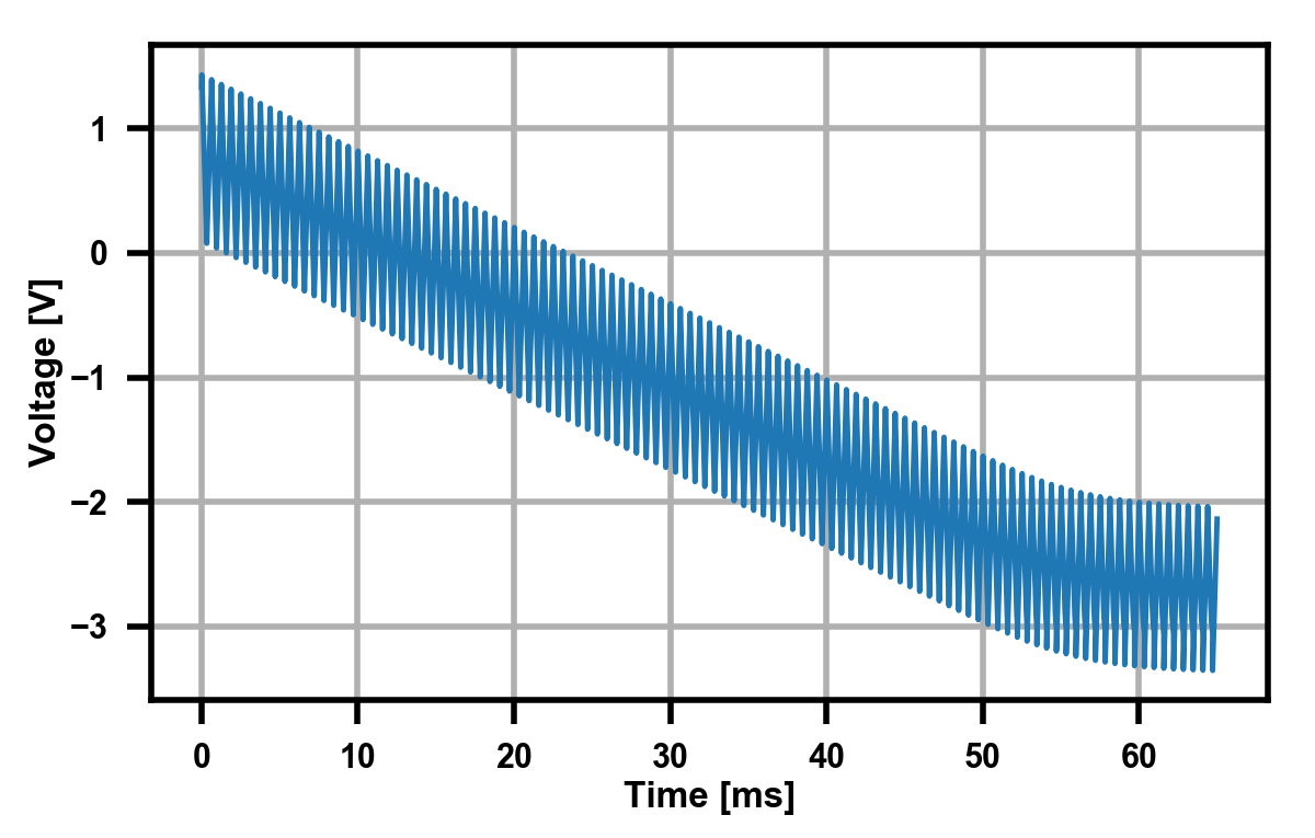
Voila, validation. Note - if you use an ideal op-amp, this won't happen. You need to use a real op-amp model with some defined input offset voltage. Anyways, we can consider our triangle wave generator done for now.
Sine Wave
Alright, let's finish this! Last step - triangle output to sine output. The simplest way to create one of these is just by using a lowpass filter. Looking at a triangle wave as a Fourier series, we get:
$$V_{TRI} = \frac{8}{\pi^2}\sum_k (-1)^k \frac{\sin(2\pi(2k+1)ft)}{(2k+1)^2}$$
While all of the \(2k+1\) might seem ugly, it's just a mathematical way of saying “all odd values of \(k\)". Now that we know it's just a sum of sinusoids, all we have to do is remove all those higher order harmonics. After that, we'll be left with out desired (albeit slightly attenuated) sinusoid. I'm not terribly concerned about “signal purity” or THD here - something around 5% should be fine.
For this, a second order low-pass filter should be good enough. There's lots of choices, but one of the most popular ones is the Sallen-Key topology. The analysis of this filter is a bit advanced - not exactly something I'd love to write up due to it's wordiness. Plenty of great derivations already exist: TI, ADI, but of course, there's nothing better than a plug-and-chug calculator.
From above, we estimated a frequency of around 1.6 kHz. I estimated a cutoff frequency of 2 kHz just in case, and threw that into the calculator. I just used unity-gain configuration for now, but in reality I'll calibrate that out later. Let's see how it does:
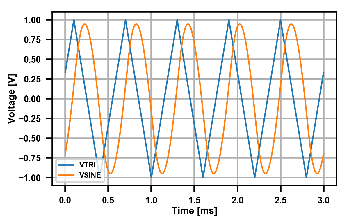
Not bad! LTSpice tells me I get around 6% THD, which is fine for me. You really only see the distortion around the peaks, they still look a little too flat for a true sinusoidal signal. This is the main reason we use the \(V_{TRI}\) input instead of \(V_{SQ}\), as we get some free high frequency harmonic suppression already by going from square to triangle.
That's it for this update. Next time I'll focus on how to connect all the various oscillators together properly and switch between them.