Tone Matrix Part 3: Adders
Now that we have all of our frequencies, we need a way to mix them all up. From a system point of view, we want to design this recursively. Each stage will have two inputs, one oscillation tone, and the previous mix. If the button is pressed, then we should add the oscillation tone to the previous mix and output that. If not, we just directly output the previous mix with no change. Some pseudo-code for this:
output = 0;
for(i = 0; i < num_levels; i++)
    if (button[i] == pressed)
        output = output + tone[i]
Or we could do it recursively:
def calc_output(output, level):
    if (level == 0):
        return 0

    if (button[level] == 1):
        return calc_output(output+tone[level], level-1)
    else
        return calc_output(output, level-1)
To do this, we'll use a circuit called a “voltage adder” (or summer). This circuit is shown below (ignore the switch for now):
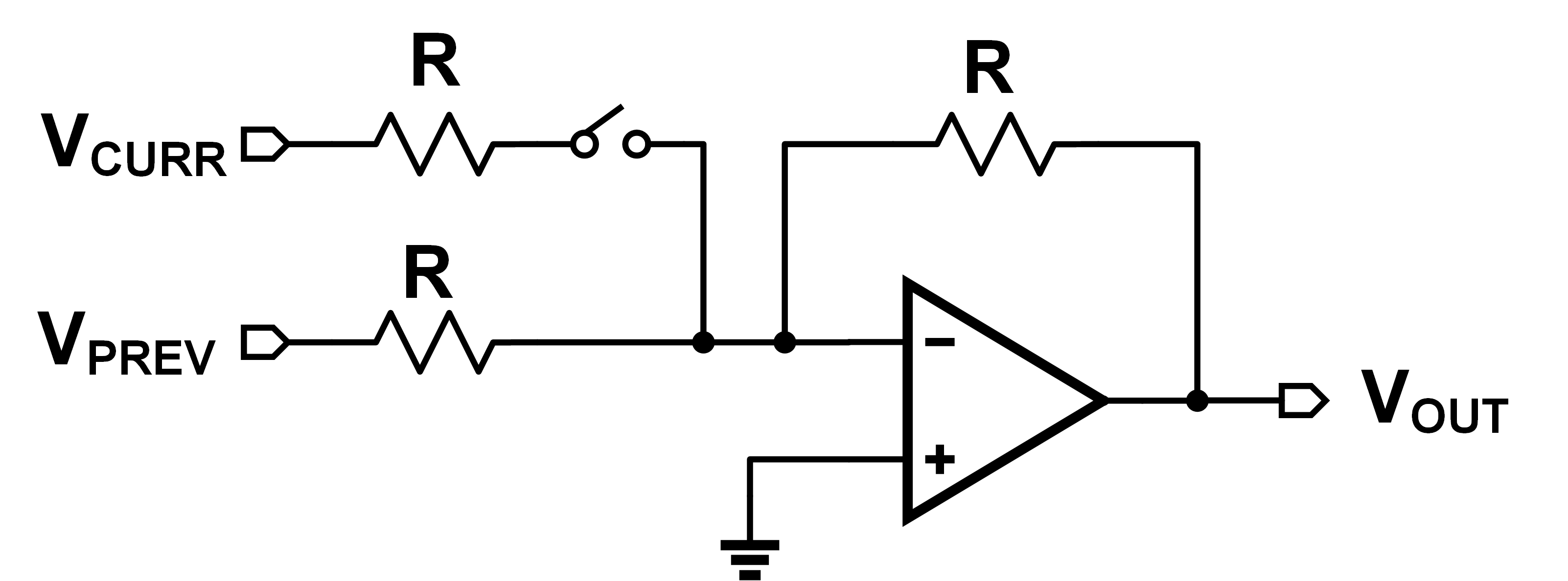
Doing KCL around the non-inverting input as usual:
\[ \dfrac{V_{CURR}-0}{R} + \dfrac{V_{PREV}-0}{R} = \dfrac{0-V_{OUT}}{R} \]
\[ V_{OUT} = -(V_{CURR} + V_{PREV}) \]
Inverting is fine! Since they're just periodic waveforms, inversion is just the same as phase shift. Now, just like we had an iterative and a recursive way of doing it in code, we have the same thing here. An iterative solution would require us to feed all our outputs into the system in parallel, like below:
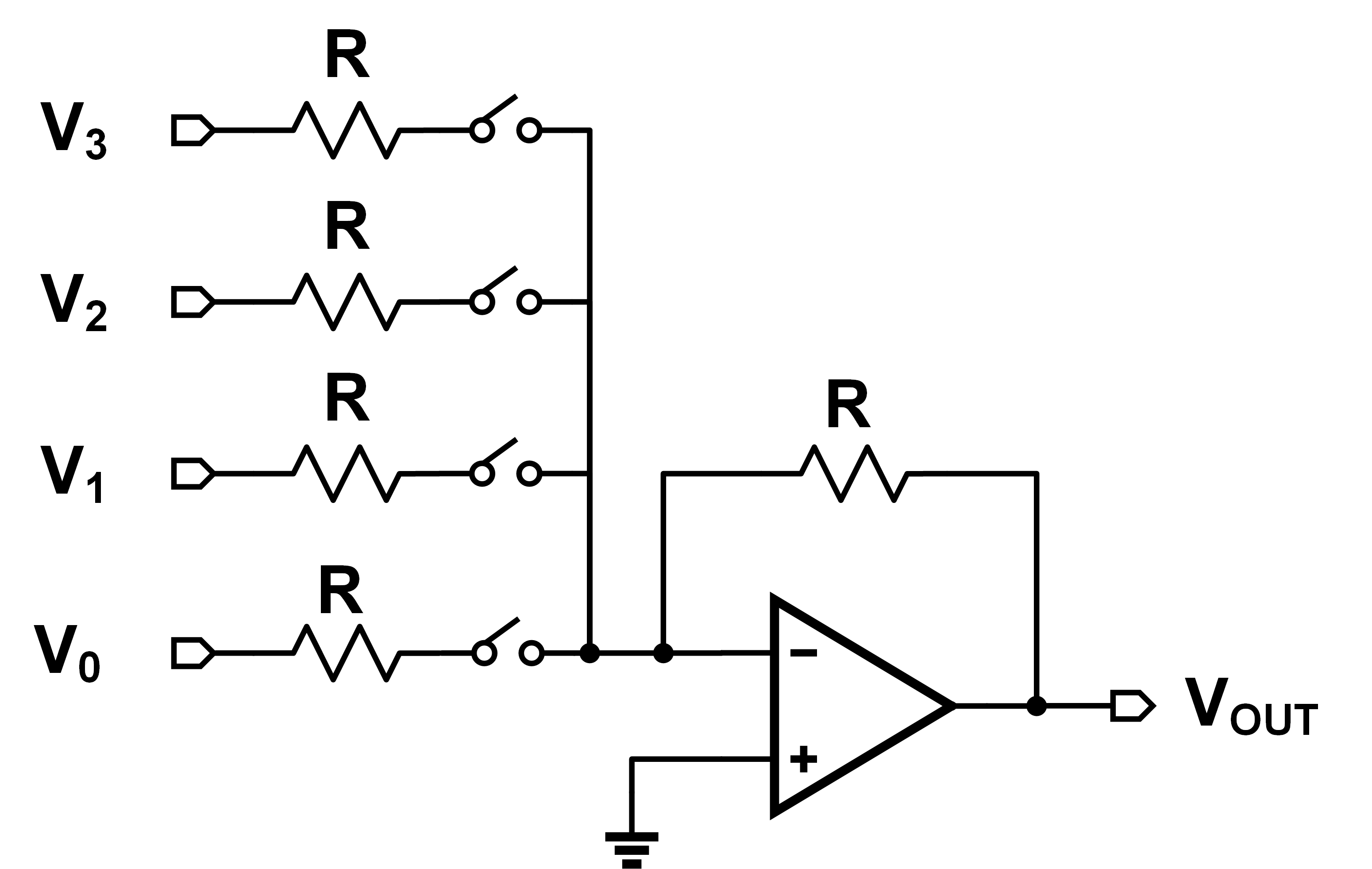
This doesn't “scale well” however. It's not very modular, and would require me to make a huge wire bus to carry all the signals down independently. Instead, we can daisy-chain individual adders, and get the output mix each time. Shown below:
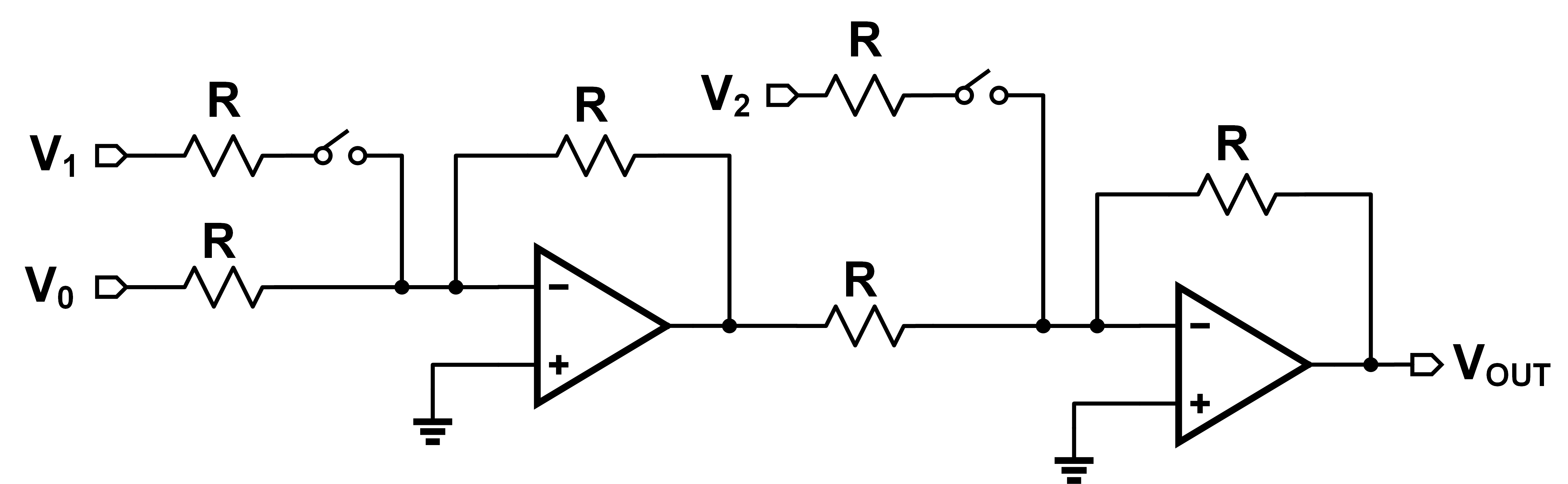
Now we can have each mixer cell with only two inputs: previous mix and current tone. We've removed the need for that huge bus, which is great! But is our output the same in both circuits? Not quite… I threw each of these together in LTSpice with three input sine waves. Each sine wave had 100 mV amplitude with frequencies of 100, 200, and 300 Hz. Here's what I got:
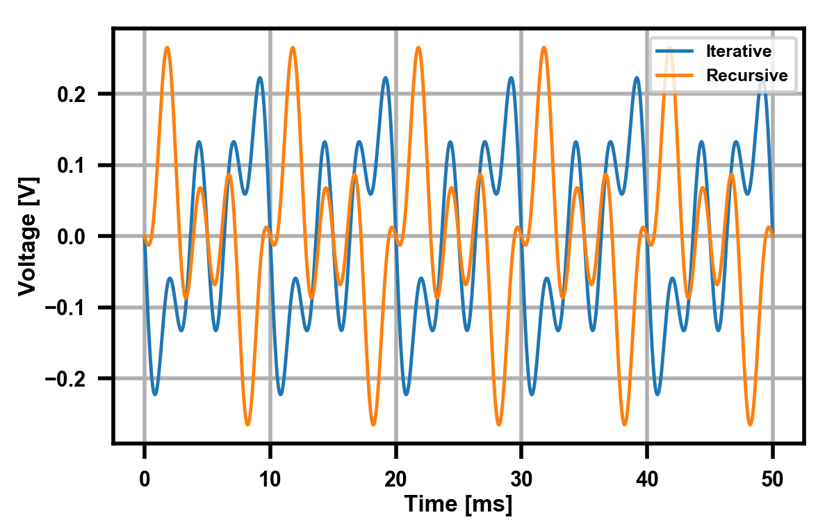
So what's changed here? It's a subtle little detail! In the iterative adder, our output is:
\[ V_{OUT} = -(V_1 + V_2 + V_3) \]
But in the recursive one, it is instead:
\[ V_{OUT} = -(V_3 - (V_2 + V_1)) = -(V_3 - V_2 - V_1) \]
The sign flip-flopping comes the fact that in the recursive one, each stage inverts as well, so each stage will alternatively add and subtract. This isn't a problem however, since like I said before, this just corresponds to a phase change in these periodic signals. As proof we can verify they have the same Fourier transform:

I got lazy and just took the FFT right from LTSpice, but you can clearly see that both waveforms have the same magnitude spectra. Therefore we can assume they will both “sound the same”. If you were really curious, you could play both signals as audio files, but I passed.