Nonlinear Devices - the BJT
Bipolar junction transistors (BJTs) are some of the most common elements in analog circuit design. They're used for gain, filtering, buffers, converters, mixers, and so many other core blocks. These are significantly harder to understand from a solid state physics background, so I'm not going to talk about that here in too much detail. We can think of it as two diodes placed back to back in series, so we have two types of BJTs: npn (np-pn diodes), and pnp (pn-np diodes) This is our first three terminal device, and accordingly, it has three states.
The easiest way to think of BJTs is to imagine them as electronic switch. We have three terminals: base (perpendicular in the schematic), emitter (with the arrow), and collector (the other one). By changing the current to the base, we can can change the current through the collector. For an npn BJT, applying a current through the base-emitter means we'll allow current to flow through the collector-emitter. This is a bit weird to think about without a circuit, so let's make one.

Like I said before, we have three modes to choose from, all of which are dependent on where we put the voltages Vb, Vc. If they're both very small, the transistor is just off, and doesn't do anything. If we raise both Vb and Vc, but keeping Vb larger, we move into saturation mode. Here the output is dependent on both the input voltage and current. Lastly, if we raise them both but keep Vc greater than Vb, we go into forward active mode, where the output is only a function of the input current. In text form, it's a bit dense, so let's put it into a table (where Vc, Vb, Ve is the voltage at the collector, base, emitter, respectively).
| Node Voltages | Mode Name | Function |
|---|---|---|
| Ve > Vb > Vc | (Cut) Off | Not much! Transistor just sits there doing nothing, conducting no current |
We can think of this circuit as two current loops. One loop goes from Vb to Rb to the base to the emitter back to Vb. The other loop goes from Vc to Rc to the collector to the emitter back to Vc. By changing the amount of current through the first loop, we can change much how current goes through the outer loop. Let's visualize this graphically now (courtesy Wikipedia).
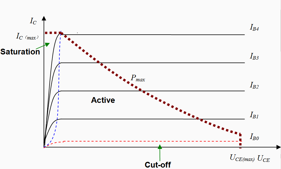
Ignore the thick red dashed line for now. The axes here are Vce - the voltage across the collector-emitter junction, and Ic, the current through the collector. Each increasing line shows an increase in the base current Ib. With very low base current, we're in the cut off mode, and the device doesn't do much of anything. With a very low voltage across the junction, we have a linear curve. We can increase the output current by either changing the voltage across that C-E terminal or the current into the base. After a certain point, the line becomes horizontal, and we only have the base current to change it in forward active mode. The blue dashed line shows the curve where we transition from saturation to active mode. In active mode, the device is called a “current controlled current source”, which makes sense, since the current output is just a function of our current input!