Research Update 3/29/16
Woohoo! Decent breakthrough today. Figured out how to model certain key characteristics of my ROI HPF. I was stumped on what seemed to be a lowpass characteristic in my transfer function, specifically the noise in the stopband. There was a constant noise floor, then a -3dB point, then a much lower noise floor in my passband. I figured it was an artifact of quantization noise in my FFT, but that didn't seem likely.
What did it up end being? An artifact of the phase noise from the VCO. The phase noise is a one pole/one zero system, with the pole at DC and the zero at some farther out point (10MHz ish?) where thermal noise dominates. This kind of looks like:
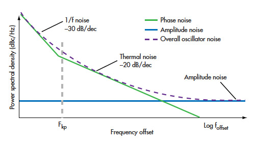
So we overlay that on a highpass filter, the rising magnitude cancels exactly with the falling magnitude of the thermal noise here. This gives us the flat band of our noise! From there, we have a lowpass element, which means that the we hit the filter's cutoff frequency. After that, the filter has a constant magnitude change, and the phase noise continues to roll off, which also aligns with our expectations. Finally, we hit a “true” noise floor in our passband.
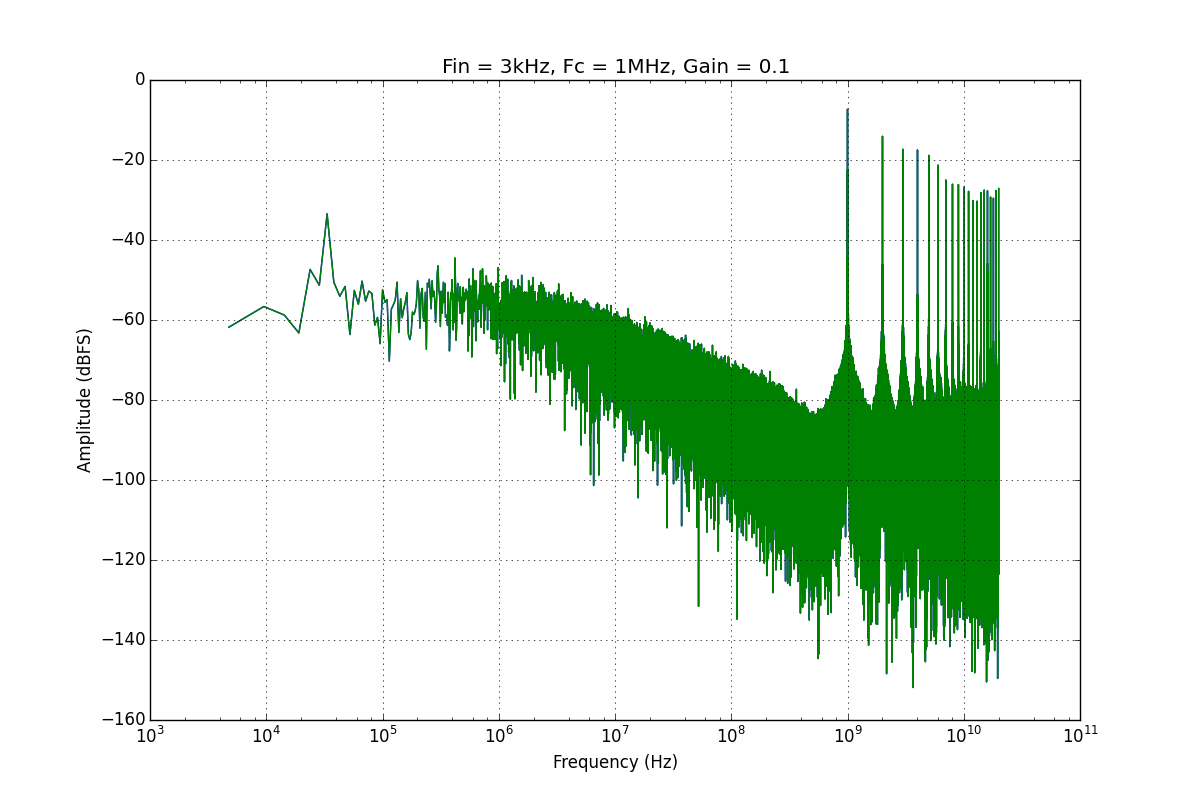
If we want to lower this stopband noise limitation, we can increase our loop gain. I did this by putting a gain element between the error signal (Vout) and the input to the VCO. There's a trade-off however, and that is the more we exercise our VCO, the higher our distortions will be. We can think of this as trading SNR for SFDR, and thinking of what we want to maximize. Shown below is a nice gif I want showing the tradeoffs when sweeping the gain of that feedback element.