Interleaving Converters
Finally, back to tech material! One of my favorite things in power electronics is the idea of interleaving power converters. There's a few rather complex derivations of it, but I think starting with an intuitive one is far easier. No worries, we'll get to boring equations by the end of this. Anyways, let's start with some background. Switching DC/DC converters (buck, boost, etc) are great because they allow us to go from one voltage level to another voltage level in a super efficient manner. Unfortunately, the name “DC/DC converter” is a bit deceptive - while we get DC in and DC out, we're basically modulating by our switching frequency middle. This means we often end up adding fairly high determinstic noise to our output - in other words, ripple.
Let's start with the classical example - a buck converter. Looking at the block diagram below:
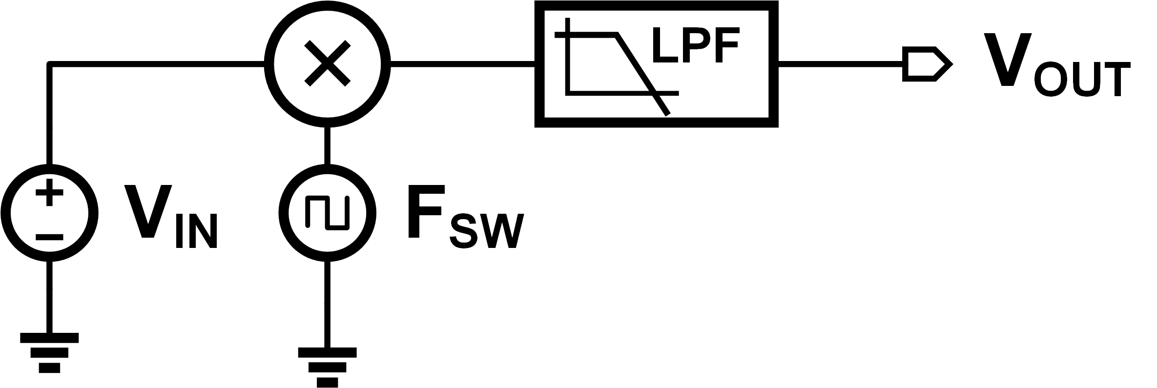
We can see that unless we have a perfect low pass filter, some of our modulated tones are going to leak into the output. Since perfect lowpass filters don't exist, this mean our ideal DC output waveform will have some noise on it. Since we modulate with a square wave, low-pass filtering that gives us triangular edges. This means our output normally looks something like:
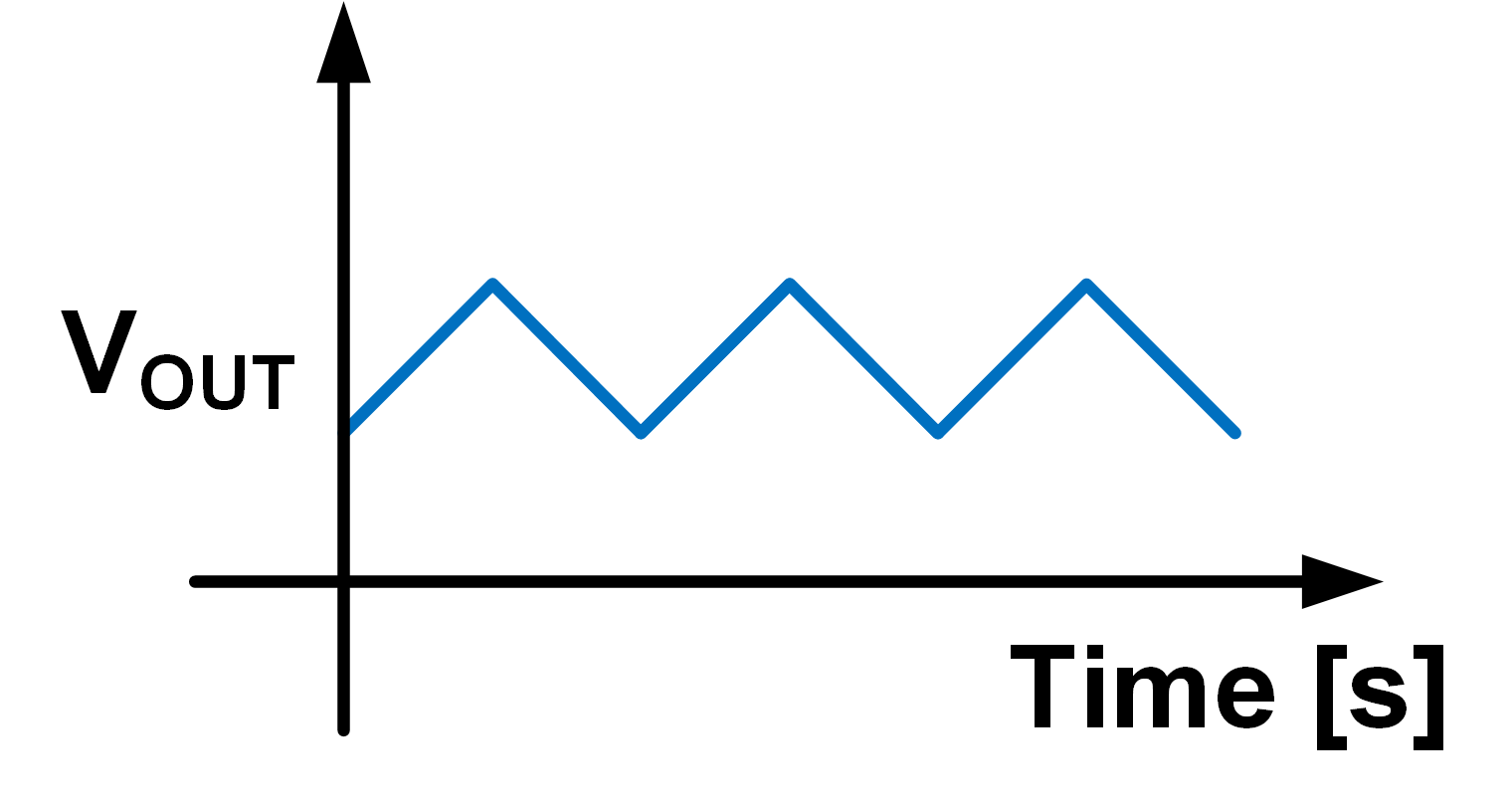
Our average DC value is correct, but there's some triangle waves riding on it. The naive way to get rid of that triangle wave would be to either
- Make the filter better, or
- Make the modulation frequency higher
Unforuntately for power electronics designers, both those ideas are pretty bad. A slightly more clever way would be to approach it from a geometric angle - if I want to get rid of any signal, why not just add the opposite to it? If I do a super simple model of my system, I can say:
$$ \rm I_{out} = \frac{1}{D} \times I_{in} + I_{tri}(t) $$
Where I'll hand-wavingly say $I_{tri}$ is my ripple waveform, and $D$ is my duty cycle. What if I casually add another input?
$$\rm I_{out} = \left(\frac{1}{D} \times I_{in} + I_{tri}(t)\right) + \left(\frac{1}{D}\times I_{in} + I_{tri}(t+\Phi)\right)$$
Why did I switch from voltage to current? Voltages don't really add nice, but currents do1. The only thing that changed between Equations 1 and 2 was that I accidentally doubled the output current - no worries, we can just reduce $I_{in}$ by a factor of two, and then we get the same output. If choose $\Phi$ just right, then I can get the ripple signals to cancel out! No ripple means perfect DC - in fact, I wouldn't even need a filter that point, how cool is that? Super cool - but lots of things are possible in the math domain, let's try in it in the real world. The schematic looks something like:
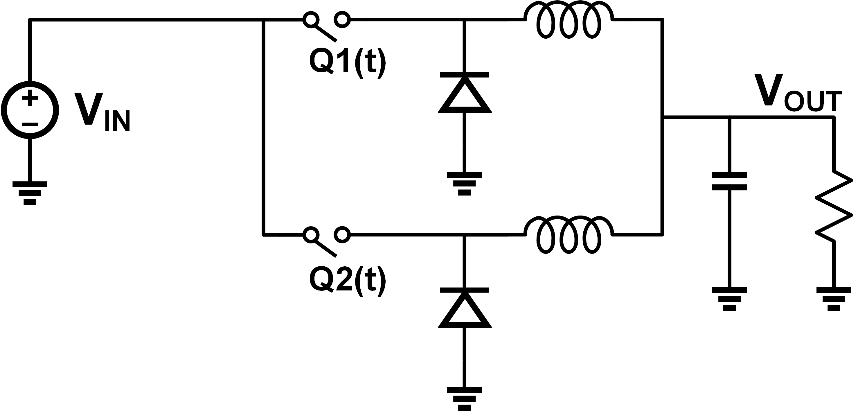
This process is called interleaving, and I owe a huge shout-out to Prof. Pilawa for introducing it to me in his grad class. If we set Q2 to be completely out of phase with Q1, we get the following output:
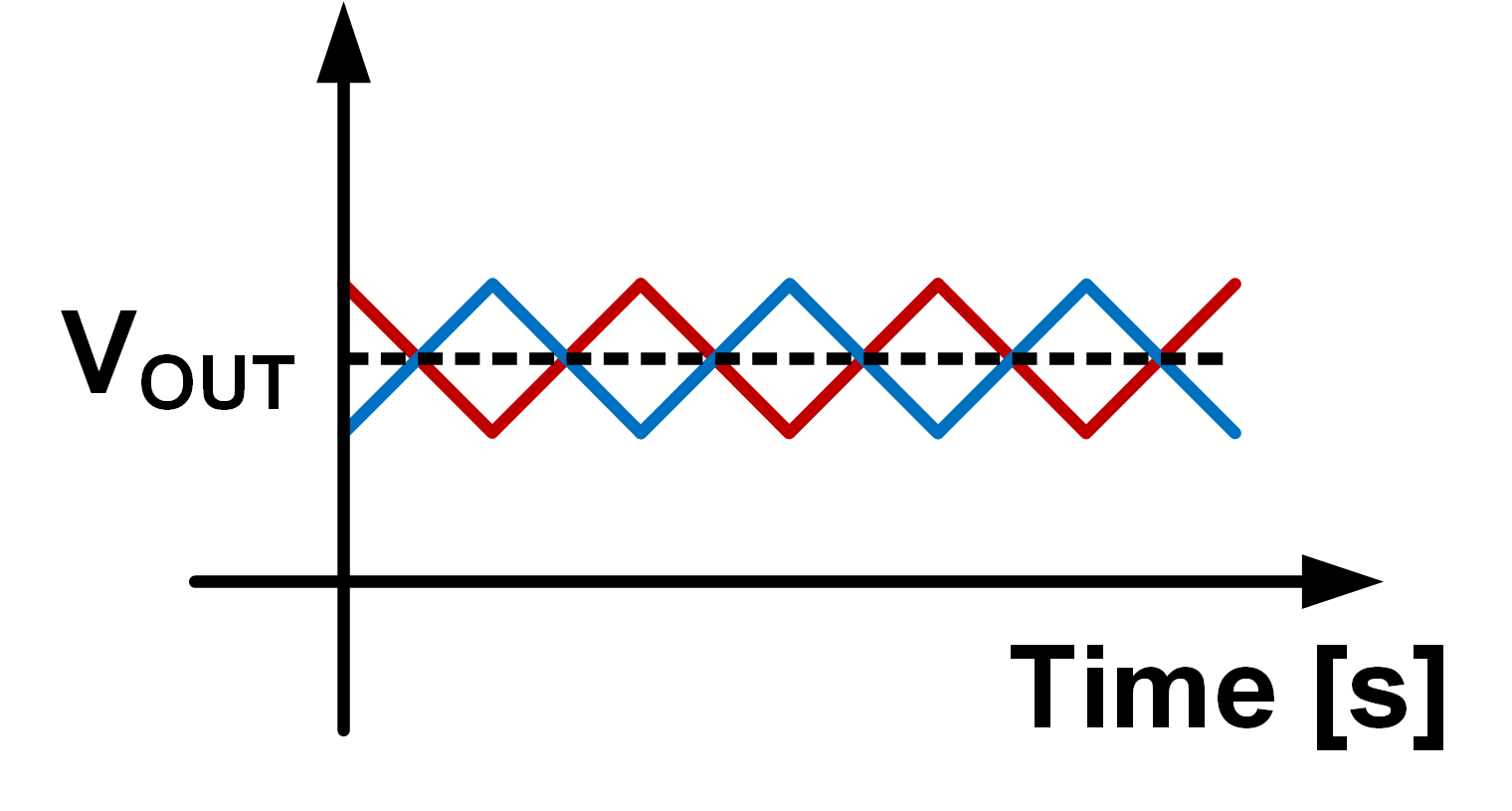
The red wave comes in from the induced ripple of Q2, and by the magic of superposition, exactly cancels out the previous ripple! Cool, it works in real life too… under some very particular circumstances. It's not always possible to get perfect ripple cancellation - it's very much a function of the duty cycle, phase offset, and number of branches. Solving this theoretically is quite painful and very geometric - one of my homework problems in grad school aws coming up with the solution with two of three conditions locked. I've rewritten it in terms of pure geometry, no power electronics needed. Try it out!
Let's define two waveforms - Input and Offset. They are both continuous piece-wise linear functions. Input is defined as:
- Linear from $(0,0)$ to $(D,V)$
- Linear from $(D,V)$ to $(1,0)$
Offset is phase-inverted version, and is defined as:
- Linear from $(0.5, 0)$ to $(0.5+D, V)$
- Linear from $(0.5+D, V)$ to $(0.5+D+(1-D), 0)$ (more simply, $(1.5, 0)$)
where $0\leq D \leq 1$ and $0 < V$. Both signals are periodic with a period of 1. In other words Input(t) = Input(t+1) = Input(t+2), and similarly for Offset.
Calculate Output = Input + Offset. There's two solutions - one for $D\gt 0.5$ and one for $D \lt 0.5$. Have fun!
Of course, that's just one case! What about every other case? While I'm impressed that some smart people have been able to find a formula for it, I can't derive it2, so I'm not going to copy paste it. Formulas without explanations? Not on my blog! The next option is to just solve it empirically and calculate it - sounds good to me! You can find the code here - I hope it's readable enough. I may have slightly abused my voltages and currents, but the output is all that matters! Let's see what we get.
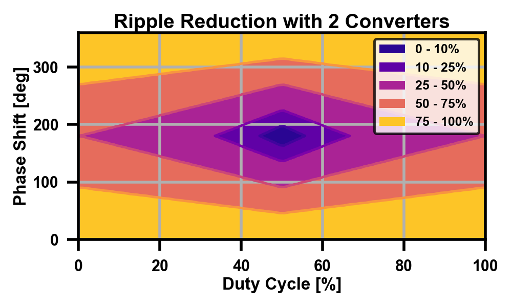
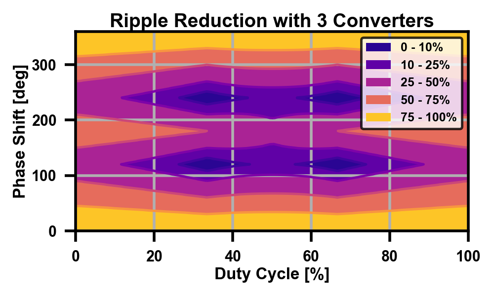
To be explicit in the legend - it's the percentage of the normal ripple, or the reduction coefficient. An absolute perfect cancellation would be 0%, and the worst case when everything is in phase is 100% (same as not interleaving at all). There's definitely some intuition for the smaller numbers, as it makes sense that with only two branches, the best point would be equal and opposite. In general, with N branches, I'd expect to see the global minima occur at:
- Duty cycles of
k/N, for integerk - Phase offset of
k*360/N, for integerk
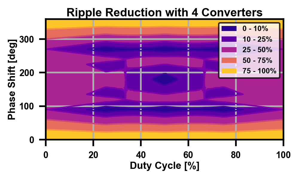
Those all show up, so the math checksout. Once you start climbing up in converter count though, there are some non-obvious minima as well. Even more interesting is that these graphs only hold true assuming all branches contain equal amounts of current - what if they don't? More math!