Eye Diagrams
As a followup from last time, I wanted to take a second and talk about visualizing another way these bitstreams we generated last time. We saw that with even mild amounts of capacitance, the bitstream gets totally ruined! But ruined isn't really a great word when it come to actual technical definitions, so let's try and define something.
Below is the input bitstream we generated before. In case it's not clear, we're using NRZ (non-return to zero) data, meaning that if we send multiple +1's in a row, we're going to maintain that level, rather than having a reset and set each clock cycle.
But let's think of this in a different way. Rather than have a continuous stream of bits, instead we can look at each possible slice. In the input bit stream, we only have four possible combinations (again assuming NRZ). We can go from {LOW, HIGH} to {LOW, HIGH}, so let's look at what each state appears as.
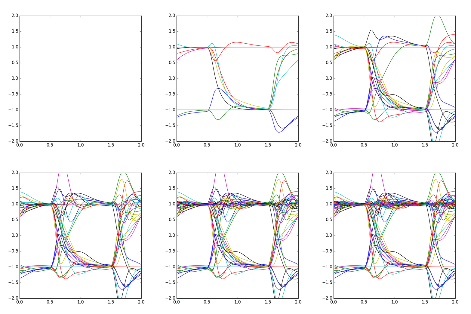
Yeah, pretty boring. Nothing interesting there. Let's compress that view point down though, and just overlay them all at once. This is the beginning of what we call an eye diagram.
Now that's a slightly weird, new picture. A good eye diagram is once that maximizes the area of the eye (the area between transitions). The majority of these links posts are going to be about taking poor eyes and widening them, either by doing some modifications to what we actually transmit, filtering in the middle, or playing tricks with the receiver.
Why does it look so ugly? Well if we remember our impulse response from before, we had those little bumps (reflections) show up after the pulse. The problem is that each individual bit we send has it's own reflections, and they all end up adding together in nasty ways. But how does that actually affect our data? Let's try generating an eye diagram of that ugly bitstream. I'll show it additively to make it clearer:

Now it's (hopefully) pretty clear what I meant by trying to widen the eye (the space between transitions). This makes our receiver much harder to design, as we need to either have a much more accurate sampling point (where in the eye to we pick the signal) or a higher resolution receiver (mapping a value like 0.7 to +1). In that first time transition, from 0.5 to 0.75ns, we say the eye is “partically closed”, because we are unable to determine which bit is which in that area. As long as the eye isn't fully closed, we can work with it (in theory).
Most eye diagrams don't show individual transitions like this, and instead show heatmaps of the rising and falling edges instead. This way we can get numerical answers (average height/width, RMS values) and categorize them appropriately.


